VL Myrsky II Structure
The Fuselage
The fuselage frame is welded steel tube structure. The cross section of the structure is box. The engine stand was attached by four bolt to frame structure. Part of vertical tail belong to the frame structure. The rest of vertical tail and horisontal tail are wooden structure covered by plywood. The rudder and elevators are duralumin structure with fabric covering.
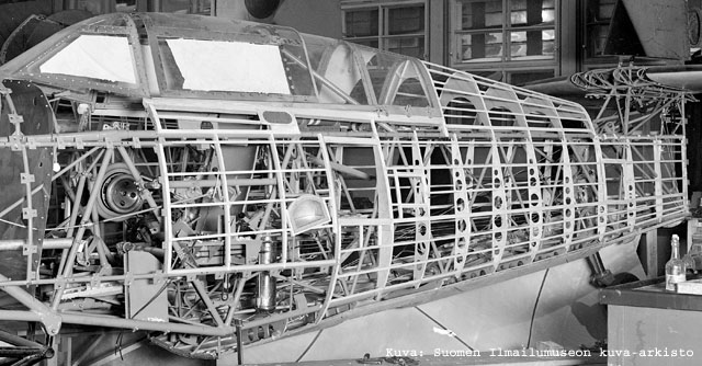
Photo: The uncovered fuselage of MY-11 (VL Myrsky II)
The rounded cross section has been built by using wooden formers. The front part of the fuselage is covereg by duralumin sheets and the rear part by birch plywood.
The Wing
The wing is a wooden structure. Spars are box beams with three plywood waists. The upper spar edge is made from pine and the lower from laminated veneer lumber. The spars divided plywood ribs to three parts.
The tapered wing has different profile in wing root (NACA 23015) and tip (NACA 23009). The span is 11.00 meter.
The wing is covered by plywood. In the Myrsky prototype the plywood covering was 6 mm thick in wing root and only 1 mm thin in wing tip. In the preproduction serie (VL Myrsky I) the was thinned by 0.5 mm on the average in order to reduce weight. Diagonal plywood (the veneer grain is in the 45 degree angle agains the sheet edge) has been used in the most stressed parts. Otherwise regular aircraft plywood has been used.
The landing flaps are duraluminum structure.
The Undercarriage
The retractable main landing gears are attached to the main wing spar. Both main and tail undercarriage have suspension strut with a steel spring and hydraulic shock suspension. The main landing gear is moved by an electric motor situated in fuselage after cockpit. Same engine is used to move landing flaps. There is a manually operated backup system, too.
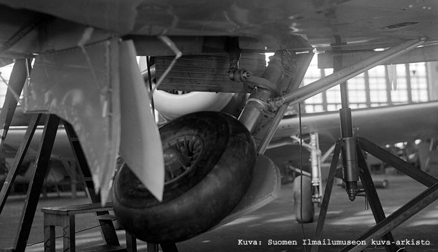
Photo: The retachable undercarriage. The wheel size is 650x236 and wheel manufacturer was Suomen Gummitehdas Oy (later Nokia).
The Engine
The engine of VL Myrsky II is Pratt & Whitney R-1830 SC3-G Twin Wasp. The engine is two-row air cooled radial engine with 14 sylinders. According to the aviation literature, the octane requirement is 91. The engine was used in Finland with 87 octane fuel. According to the studies of Allied forced, the German B4 was 91 octane fuel.
The cylinder capacity is 30 litres and compression ratio 6.7:1. The ratio of supercharger is 7.15:1. The diameter of the engine is 1,222 mm.
The takeoff power is 1,050 hp (1,065 metric hp) at 2,700 rpm with supercharger pressure 1.42 Bar (107 cmHg = 0.14 MPa = 20.6 Psi). The maximum period of takeoff power is 5 minutes. The critical rammed altitude with maximum power is 2,650 meters and with maximum continuous power 3,650 meters. The maximum continuous power is 900 hp (910 metric hp) at 2,550 rpm with pressure 1.15 Bar (87 cmHg = 0.12 Mpa = 16.7 Psi). The maximum cruise power is 650 hp (660 metric hp) at 2,200 rpm.
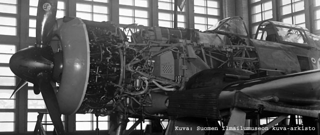
Photo: The uncovered front fuselage of MY-5 (VL Myrsky II).
The voltage of electrical system is 24. The generator is either 1 kW Durcellier or 600 W Scintilla. There are two 30 Ah Varta 6 DL 4 accus in series. They are situated in fuselage after cockpit. The electric equipment in the aircraft are engine starter, lights, some instruments, electric motor of undercarriage and flaps, control motor of cowling gills, radio, sight, machine guns, camera, konekiväärikameralle and heating.
The fuel tank is made from aluminium sheet and covered by 6 mm thick rubber. The tank is situated in the fuselage between the engine and the cockpit and attached to the fuselage by steel bands. The capacity of the tank is 300 litres. There are possibility to use two drop tanks, each 150 litres. The drop tanks are made from cross laminated veneer. The fuel is moved from drop tanks to the main tank by air pressure. The automatic system keep the main fuel tank full until the drop tanks are empty.
The oil tank is situated on the firewall. The capacity of oil tank is 36 litres. The tank has electric heater as well as the engine has block heater. There is system to thin lubrication oil by fuel during winter time.
The engine has NACA ring made from aluminium. There is none exhaust collector. The exhaust pipes are collected to two group and equipped with ejectors. The cowling gills move longitudinally by electric motor in order to reduce drag. The air intake is situated to the top of the cowling.
The ratio of propeller gear is 16:9. The propeller was a three-blade VLS 8002. The hub and constant speed controller are copied from Hamilton Standard in Sweden. The blades are made from laminated veneer lumber in State Aircraft Factory. The spinner has short blades to enhance engine cooling.
The Cockpit
The pilot seat is made from 10 mm steel plate and covered by felt and leather. There is a hand wheel to adjust the elevation of the seat. The sealt belts are attached to the seat or fuselage.
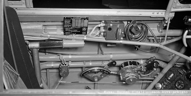
Photo: The left hand side of the cockpit.
The control stick has circular grip and has an electric firing handle. The food pedals can be adjusted longitudinally by an control wheel. The tail undercarriage can be attached to the pedal by lever.
The throttle lever and mixture lever are situated to the left hand side of the cockpit. The lever of boost pressure limiter is attached to the throttle lever. The mixture lever has four set values: full rich, automatic rich, automatic weak and stop. Usually "the automatic rich" was used and the system adjusted the right mixture during all throttle settings and flight conditions. During cruise "the automatic weak" can be used but the power changes are not possible. "The full rich" was used only if the automatic control was out of order. There were a separate lever for propeller pitch adjustment.
The selector lever of undercarriage and flap is situated to the right hand side of the cockpit. There is hand wheels of manually operated system.
The hand wheels of elevators, rudder and ailerons are situated to a box in the left hand side of the cockipit. There is manual fuel pump, too.
The instrument panel is divided to three parts. There is an additional panel below the main instrument panel between legs of pilot for main electric couplers. The charging grips of machine guns were situated to borders of the instrument panel and adjustment of the cowling gills right hand side of the instrument panel.
The sight TH-m/44 KK was designed by Vilho Väisälä (later Vaisala). The FuG VIIa radio uses frequency range between 2,700 and 3,750 kHz taajuusalueella toimiva. The weight of the radio is 18 kg. The range to fixes station is up to 110 km and to other aircraft between 60 and 80 km.
The cockpit canopy slides longitudinally and can be locked to intermediate positions. The usage of the armament soot the windscreen. It can be cleaned by fuel spray.
The cockpit arrangement was successful and it was copied directly to the VL Pyörremyrsky.
The Armament
The armament comprise of four Finnish VKT 12,70 LKk/42 machine guns. The caliber of the machine guns is 12,7 mm. The armament is situated on the top of engine cowling. The armament is syncronised to the propeller and the rate of fire is depending of the propeller speed. The rate of fire was 1 100 round per minute without syncronisation.
The elevation of the machine guns is 1 degree 20 minutes. The trajectories cross the sighting line 400 meters in front of aircraft. The trajectories are sweeping as far as 600 meter with burts fire. With sustained fire the barrel overheated and the trajectories are curved and power weaken.
The outermost machine guns have 260 rounds each and the inner 220 rounds. There are collection boxes for empty cases.
There were none bomb racks in the original spesification of VL Myrsky II. However, the aircraft has two hard points for drop tanks. Therefore two bomb racks for 50 to 100 kg boms added to spesification during the summer 1944. Only boms equipped with point fuzes can be used. There is an emergency launcer in order to release bombs as duds.